Pages

Showing posts with label Network Management. Show all posts

6over4 Tunnels Configuration - (Mechanisms of transition from IPv4 to IPv6)

One of the most common mechanisms for testing IPv6 network interconnection, are 6over4 tunnels, which are used to encapsulate IPv6 packets in IPv4 native network, creating a peer to peer network between two machines that are communicating by this protocol .

Normally an IPv6/IPv4 node, or dual stack, in order to communicate with another computer through an IPv4 network, you need a tunnel interface, in which IPv6 addresses are configured as shown in the graph.

Tunne IPv4

6over4 Tunnels Configuration

Configure the tunnel 6over4 is in principle a relatively simple task, the configuration is similar to that performed in a GRE tunnel

For configuration, you must define the start and destination addresses on both computers, in some cisco equipment does not allow defining the start address, so they can define the start of the tunnel through the interface with local public IPv4 address. To 6over4 tunnel configuration is not necessary to define an IPv4 address.

Router1#configure terminal 
Router1(config)#interface Tunnel10
Router1(config)# ipv6 address 2800:100:101::1/64
Router1(config-if)#tunnel source 154.54.6.5
Router1(config-if)#tunnel destination 206.167.13.198
Router1(config-if)#tunnel mode ipv6ip
Router1(config-if)#end
Router1#

On Router 2, you must create another tunnel interface, as Router 1, and associate the source and destination addresses.

Router2#configure terminal 
Router2(config)#interface Tunnel20
Router1(config)# ipv6 address 2800:100:101::2/64
Router2(config-if)#tunnel source 206.167.13.198
Router2(config-if)#tunnel destination 154.54.6.5
Router1(config-if)#tunnel mode ipv6ip
Router2(config-if)#end
Router2#

As discussed above in some cases the equipment can not define the starting IP address, so you will need to specify the start of the tunnel with the physical interface name, for our example, will the interface f0/0, the command will be the following: "Router2 (config-if) # tunnel source int f0/0".

At the end of these configurations, the resulting topology will be as shown in the graph below, with an interface Tunnel10 in router1, connected with a direct cable to Tunnel20 interface on Router 2 and allow the simulation of having a link dedicated to communicate via IPv6, this is a simple way to interconnect their networks for IPv6 testing.

Tunnel for IPv6

Routing traffic through the tunnel 6over4

The next step now will allow routing from network 2800:20:20 :: 0/64 with the network 2800:10:10 :: 0/64. This is very simple, just simply turn on IPv6 routing and then add a route to reach the other network, the commands needed are:

Router1(config)#ipv6 route 2800:10:10::/64 2800:100:10::2
Router1(config)#ipv6 unicas-routing
Router2(config)#ipv6 route 2800:10:10::/64 2800:100:10::1
Router2(config)#ipv6 unicas-routing

Read more

Configuring GRE Tunnels with Cisco routers

GRE (Generic Router Encapsulation) is a protocol that can encapsulate a wide variety of different protocol types inside IP tunnels, creating a peer to peer network between two machines that are communicating by this protocol. Its main use is to create VPN tunnels. GRE is defined by RFC 1701, 1702 and 2784.

It is important to understand the need to make when configuring GRE tunnels, it could be difficult to manage if the number of them grows too. These tunneles turn out to be useful when you need to work with a protocol that is not routable as NetBIOS, or IP routable protocols other than through an IP network. Currently the use of GRE has become a major transition mechanisms for IPv6 network deployment. This means you can connect two IPv6 islands over IPv4 tunnel.

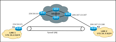
Tuneel GRE - starting

Configuring GRE Tunnels

Configure the GRE tunnel is in principle a relatively simple task, just define the start and destination addresses on both devices and create the tunnel interface. To run the example will use Cisco 2800 series routers, although it is possible to make a tunnel with a variety of equipment.

Router1#configure terminal 
Router1(config)#interface Tunnel10
Router1(config-if)#ip address 192.168.2.6 255.255.255.252
Router1(config-if)#tunnel source 154.54.6.5
Router1(config-if)#tunnel destination 206.167.13.198
Router1(config-if)#end
Router1#

On Router 2, you must create another tunnel interface, as Router 1, and associate the source and destination addresses.

Router2#configure terminal 
Enter configuration commands, one per line.  End with CNTL/Z.
Router2(config)#interface Tunnel30
Router2(config-if)#ip address 192.168.2.5  255.255.255.252
Router2(config-if)#tunnel source 206.167.13.198
Router2(config-if)#tunnel destination 154.54.6.5
Router2(config-if)#end
Router2#

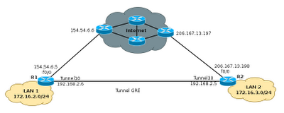
At the end of these configurations, the resulting topology will be as shown in the graph below, with an interface Tunnel10 in router1, connected with a direct cable to Tunnel30 interface on Router 2.

Tunnel GRE

The next step now will allow routing from 172.16.2.0/24 to 172.16.3.0/24. In practice this is simple and does not hit the network performance, thus creating tunneles, can solve many problems of connectivity between remote sites without much complexity. The only thing that should be taken into account when creating the tunneles is no mistakes with the start addresses and destination.

Commands to configure static routing:

Router1(config)#ip route 172.16.3.0 255.255.255.0 tunnel 10 192.168.2.5
Router1(config-if)#end
Router2(config)#ip route 172.16.2.0 255.255.255.0 tunnel 30 192.168.2.6
Router2(config-if)#end

Selecting the type of tunnel to use

When you create a tunnel, usually do not specify the protocol to use, so that devices default, select the GRE protocol. However it is possible to define the protocol, by a single command, as shown below:

Router1(config)#interface Tunnel1
Router1(config-if)#tunnel mode ipip 

Ipip mode is the type of tunnel that allows IP packets encapsulated within another IP packet, very useful to allow communication between IPv6 networks through IPv4 networks. The process for selecting the protocol is simple and need to be configured on both sides of the tunnel, as defined ipip protocol can also select any of the following: AURP, Cayman, dvmrp, eon, gre ip, ip gre multipoint, ipip, iptalk.

Read more

Installing Cacti server (Linux server cacti)

Cacti is an open source tool that allows a network administrator to know the link status, availability of network devices, among other things. This knowledge is important because it allows you to plan, book and manage efficiently the resources of a LAN.
Logo Cacti

Requirements:
  • Distribution: Kubuntu 9.04
  • Software: cacti (hobbit-4.2.0.tar.gz), apache2 (apache2.2.9)
  • Server: netadmin (IP-Addr: 192.168.1.5)

Cacti Server Dependencies

Cacti requires that the following packages are installed on your system.
  • RRDTool 1.0.49 or 1.2.x or greater
  • MySQL 4.1.x or 5.x or greater
  • PHP 4.3.6 or greater, 5.x is recommended
  • Web Server, Apache2 for this manual.

Name required packages
  • httpd
  • php
  • php-mysql
  • php-snmp
  • mysql
  • mysql-server
  • net-snmp

Installing Cacti program

netadmin @linux:~ > apt-get install cacti

Note: During this process, it will install all dependencies that cacti need. (Only debian based operating systems). In Kubuntu, Cacti for a password for the database during this process. So no need to perform subsequent configurations.

Cacti Server Basic Configuration

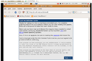
Once completed the installation process of packages, we proceed to the configuration is done through a web browser.
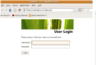
Configure Cacti

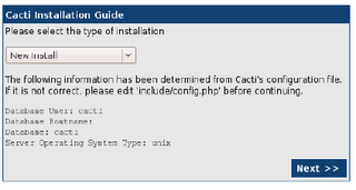
As this is a new installation, you only need to click on next.
Configure Cacti page 2


This section asks the user key administrator for the first time, the User Name is "admin" and password: "admin". Cacti, then request the change of the password for the admin user
Configure Cacti - username

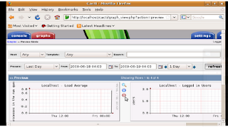
By default, the first time Cacti allows access to the admin account with admin password, then you make this change, you can view images of the home team. Cacti can monitor only the local computer, then you have to configure the control of other computers.
Configure Cacti - admin

Add a new device

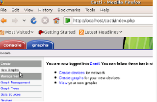
To add a new device (servers, switches or routers) must enter the Console tab and then select the item New Graph.
Configure Cacti - add device

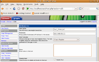
This section introduces the details of equipment, such as IP address, device description (important to identify it) and type of device.
Configure Cacti - detail new device
Configure Cacti - detail new device part 2

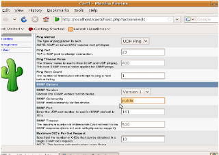
This is a continuation of the previous screen is used to configure the communication mechanism of Cacti with the device, either through ping or snmp, snmp is best done by, and is also recommended to configure an SNMP community other than public


Creating new graphics on the device
Configure Cacti - new graphics

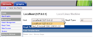
To add a chart to an existing device, you must enter the Console tab and then select the item New Graph.
Configure Cacti - new chart

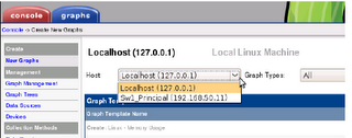
At this stage, Cacti, equipment selection requests which to generate the new graph
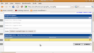
Configure Cacti - generate new graph

As shown, it is only necessary to perform a check on the new graph needs to be created.

Once you do this, the process is the same for adding new switches and routers. Cacti also allows many other options, however, this will allow you to start working with a very good system to control the bandwidth being used on the network.

Read more

Hierarchical Network Model - Network Design

To build a LAN, it is necessary to take into account many aspects to the network meets the needs of small and medium enterprises, ie designing the network is necessary to use techniques to get closer to success.

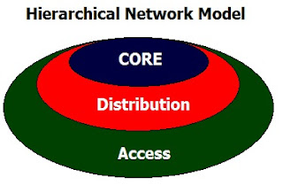
The hierarchical model has many benefits, as it allows the network more predictable. This, because the campus network is divided into layers and each layer defined in the services they provide. Compared to other network designs, a hierarchical network is managed and expanded more easily and resolve problems faster.
Hierarchical Network Model

Among the advantages that exist to separate the networks in three levels, is that it is easier to design, implement, maintain and scale the network, plus it makes it more reliable, with better cost / benefit ratio. Each layer has specific functions assigned and not necessarily refer to a physical separation, but logic, so that various devices can have a single layer or a device by the features of more than one of the layers.

The layers and their typical functions are:
  • The access layer, and controls the users access workgroup (workgroup access) or network resources. This layer performs the Ethernet switching. The access layer interfaces with end devices such as PCs, printers and IP phones, to provide access to the rest of the network. The access layer can include routers, switches, bridges, hubs, and wireless access points (AP). The main purpose of the access layer is to provide a means of connection to the network devices and control devices which can communicate over the network.
  • The distribution layer is the means of communication between the access layer and the core. The functions of this layer are to provide routing, packet filtering, access to the WAN and determine which packets must arrive at Core. It also determines what is the fastest way to meet network requirements, for example, how to bring a file from a server.
    Here also are deployed network policies, eg routing, access-list, packet filtering, queuing, security is implemented and network policies, routing between VLANs and other workgroup functions are defined domains broadcast and multicast.
  • The core layer is literally the core of the network, its only function is to switch traffic as fast as possible and is responsible for carrying large amounts of traffic in a reliable and fast, so the latency and speed are important factors in this layer.

    In case of failure, it affects all users, so that fault tolerance is important. Moreover, given the importance of speed, does not function as may increase latency, and access-list, interVLAN routing, packet filtering.

    The core layer is essential for interconnectivity among devices of the distribution layer, therefore, it is important that the core is highly available and redundant.

    The selection of switches or network equipment should be considered according to the requirements of each layer based on the hierarchical model.


In the access layer equipment can be found the following characteristics:
  • 10/100/1000 Ethernet connectivity.
  • PoE
  • vlan
  • QoS

In the distribution layer, it is advisable to purchase equipment which complies with the following features.
  • Redundant links.
  • Connections to 1G or 10G
  • Capacity Routing (L2 and L3 Switches)
  • QoS
  • High switching capacity, like forwarding high rates.

While in the core layer, the switches have the following characteristics:
  • Connections to 1G or 10G
  • QoS
  • High switching capacity, like forwarding high rates.
  • Redundant links.

Read more

Hobbit Server Configuration (Network Monitoring)

Hobbit service

Activation Process for Agent Hobbit (hobbit Linux server)

Distribution : Kubuntu 9.04
Software : hobbit (hobbit-4.2.0) , apache2 (apache2.2.9)
Servidor : Netadmin (IP-Addr:192.168.1.5)


Add hobbit user

linux:~ # groupadd hobbit
linux:~ # useradd –d /usr/local/hobbit –g hobbit hobbit
linux:~ # mkdir /usr/local/hobbit/
linux:~ # chown hobbit.hobbit /usr/local/hobbit


Hobbit installation program

hobbit@linux:~ > apt-get update
hobbit@linux:~ > apt-get install apache2
hobbit@linux:~ > apt-get install hobbit

During this process, all units installed Hobbit needs. (Only in Debian-based operating systems)


Hobbit Service Configuration

You need to setup the hobbit master file (in this file are input devices that will monitor Hobbit) (command vi /etc/hobbit/bb-hosts)

page Servers(internal) Servers(Private)

group-compress Servers(Private)

# ----------- Servers Main Building -------------

192.168.0.2 Web # NET:intern http://192.168.0.2/

192.168.0.3 DNS #

192.168.0.4 Moodle # NET:intern http://192.168.0.4/

192.168.0.5 Plone #

127.0.0.1 Local-Device # bbd http://Netadmin-desktop/

page Switches(internal) Switches(Netadmin)

group-compress Switches(Netadmin)

# ------------------------------------------------------

# -----------Switches Main Building ---------------

# 192.168.50.10 Sw1.Main #

192.168.50.11 Sw2.Main #

192.168.50.12 Sw3.Main #

##

-----------Switches Central Building ----------------

# 192.168.50.20 Sw1.Central #

192.168.50.21 Sw2.Central #

##

-----------Switches South Building----------------

# 192.168.50.30 Sw1.South #

192.168.50.31 Sw2.South #

# ------------------------------------------------------


Changing Apache2

Modify the /etc/apache2/hobbit/httpd.conf (Archive with web access policies)

Alias /hobbit/ "/usr/local/hobbit/server/www/"

Options Indexes FollowSymLinks Includes MultiViews

Order allow,deny

Allow from all

ScriptAlias /hobbit-cgi/ "/usr/local/hobbit/cgi-bin/"

AllowOverride None

Options ExecCGI Includes

Order allow,deny

Allow from all

ScriptAlias /hobbit-seccgi/ "/usr/local/hobbit/cgi-secure/"

AllowOverride None

Options ExecCGI Includes

Order allow,deny

Allow from all

AuthUserFile /usr/local/hobbit/server/etc/hobbitpasswd

AuthGroupFile /usr/local/hobbit/server/etc/hobbitgroups

AuthType Basic

AuthName "Hobbit Administration"

Require valid-user


Automatic start of Hobit

linux:~ # cp /usr/local/hobbit/server/hobbit.sh /etc/init.d/hobbit

linux:~ # chkconfig hobbit on


Setting admin password

Linux:~# /usr/sbin/htpasswd –c

/usr/local/hobbit/server/etc/hobbitpasswd admin

New password:

Re-type new password:

Adding password for user admin

linux:~ #


Restart Apache2 service

linux:~ # /etc/init.d/apache2 restart

Syntax OK

Shutting down httpd2 (waiting for all children to terminate)

done

Starting httpd2 (prefork) done


Restart Hobbit service

linux:~ # /etc/init.d/hobbit start

Starting hobbit: Hobbit started

hobbit.

linux:~ #


Check the operation

To verify the service via a web browser.
  • http://192.168.1.5/hobbit/

Read more

Inter-VLAN routing (Interface, Subinterface) - routing between VLANs

The inter-VLAN routing is needed once you have a vlan network infrastructure implemented because users need to exchange information from one network to another.

It is important to remember that each VLAN is a single broadcast domain. Therefore, by default, computers in separate VLANs can not communicate.

There is a way to enable end stations to communicate with them, this way is called inter-VLAN routing.

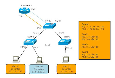
Inter-VLAN routing - 1

Inter-VLAN routing is a process that allows you to forward network traffic from one VLAN to another using a router. VLANs are associated with unique IP subnets in the network. This subnet configuration facilitates the process of routing in a multi-VLAN.

Traditionally, the routing of the LAN using routers with multiple physical interfaces. You need to connect each to a separate network interface and configure it to a different subnet.

In a traditional network that uses multiple VLANs to segment network traffic into logical broadcast domains, routing is done by connecting different physical interfaces on the router to different physical ports on the switch. The switch ports are connected to the router in access mode, in this way, various static VLANs are assigned to each interface port. Each switch interface would be assigned to a different static VLAN. Each router interface can then accept traffic from the VLAN associated with the switch interface that is connected and traffic can be routed to other VLANs connected to other interfaces.
Inter-VLAN routing - 2

The traditional inter-VLAN routing requires multiple physical interfaces on the router and the switch. However, not all inter-VLAN routing configurations require multiple physical interfaces.

Some router software allows to configure the router interfaces as trunks. This opens new possibilities for routing between VLANs. "router-on-a-stick" is a type of router configuration in which a single physical interface routes traffic between multiple VLANs on a network.

Router on a Stick
Inter-VLAN routing, subinterfaces (Router on a Stick)

The router interface is configured to function as trunk and is connected to a switch port configured in trunking mode. The router performs routing between VLANs to accept traffic from VLAN tagging on the interface from the adjacent switch trunk and internally route between VLANs, using subinterfaces. The router then forwards the VLAN routing traffic for VLAN tagged target by the same physical interface.

The subinterfaces are multiple virtual interfaces associated with a physical interface. These interfaces are configured in software on a router configured independently with an IP address and VLAN assignment to work on a specific VLAN. The subinterfaces are configured for different subnets that correspond to the VLAN assignment, to facilitate routing logic before the VLAN tag data frames and forward for the physical interface. Learn more about interfaces and subinterfaces to the next topic.

Some switches can perform Layer 3 functions, which replaces the need for dedicated routers for basic routing in a network. Multilayer switches can perform routing between VLANs.

To enable a multi-layer switch for routing functions, you must configure the VLAN on the switch interfaces with corresponding IP addresses that match the subnet to which the VLAN is associated to the network. Multilayer switch must also have IP routing enabled.

Interfaces and subinterfaces

Traditional routing requires routers that have multiple physical interfaces to facilitate inter vlan routing. The router performs routing by connecting each of its physical interfaces to a single VLAN. In addition, each interface is configured with an IP address for the subnet associated with the VLAN connected to it. When you configure IP addresses on physical interfaces, network devices connected to each VLAN can communicate with the router using the physical interface connected to the same VLAN. In this configuration, network devices can use the router as a gateway to access devices in other VLANs.

Configure the subinterface

The configuration of the router subinterfaces is similar to the configuration of physical interfaces, except that it is necessary to create the subinterface and assign a VLAN.

The syntax for the subinterface is always the physical interface, in this case f0 / 0, followed by a dot and a number of subinterface. The subinterface number is configurable, but is usually associated to reflect the number of VLANs.

Before assigning an IP address to a subinterface, the subinterface must be configured to operate in a specific VLAN using the command "encapsulation dot1q VLAN ID". In the example, the subinterface is assigned to Fa0/0.10 VLAN10. Once assigned to the VLAN, the command "ip address 172.16.10.1 255.255.255.0" assign the proper IP for the VLAN subinterface.

Router#configure terminal
Router(config)# interface f0/0.10
Router(config-subif)# encapsulation dot1q 10
Router(config-subif)# ip address 172.16.10.1 255.255.255.0
Router(config-subif)# no shutdown

Unlike a typical physical interface, subinterfaces are not enabled with the command "no shutdown" in the level so the subinterface configuration of Cisco IOS software. However, when the physical interface is enabled with the command "no shutdown", all configured subinterfaces are enabled. Similarly, if the physical interface is disabled, all subinterfaces are disabled.

One advantage of using a trunk is that it reduces the number of switch ports and router. Not only does this save money but also reduces the complexity of the configuration. As a result, the focus of the subinterface on the router can be extended to a much higher number of VLANs that a configuration with a physical interface VLAN design.

Port Limits

The physical interfaces are configured for a VLAN interface on the network. In networks with many VLANs can not use a single router for inter VLAN routing on. The routers are physically limited to avoid containing a large number of physical interfaces.

Subinterfaces allow you to extend the router to accommodate more VLAN than allowed by the physical interfaces. The Inter-VLAN routing in large environments with many VLANs can be accommodated better if you use a single physical interface with many subinterfaces.

Performance

Because there is no contention for bandwidth on separate physical interfaces, physical interfaces have better performance when compared with the use of subinterfaces. The traffic for each VLAN connected have access to the full bandwidth of the physical interface of the router connected to that VLAN.

When using subinterfaces for inter-VLAN routing, traffic is being routed competing for bandwidth on the single physical interface. In a busy network, this can cause a bottleneck in communication.

Access ports and trunk ports

The connection of the physical interfaces for inter-VLAN routing requires the switch ports are configured as access ports. The subinterfaces require the switch port is configured as a trunk port so that it can accept traffic tagged in the VLAN trunk. By using subinterfaces, many VLANs can be routed on a single trunk, instead of using a single physical interface for each VLAN.

The use of subinterfaces for inter-VLAN routing, results in a less complex physical configuration using separate physical interfaces, because the number of physical network cables that connect the router to the switch is lower. With fewer cables, less confusion about where the cable is connected to the switch. Because VLANs are interconnected by trunks on a single link, it is easier to solve the problem of physical connections.

On the other hand, the use of subinterfaces to a trunk port, results in a more complex configuration software, which can be difficult to troubleshoot if problems arise. In the model router-on-a-stick is used only accommodate a single interface for all VLANs.

If a routed VLAN have problems with other VLANs, you can not simply trace the cable to see if it is plugged into the correct port. It is necessary to verify the switch port is configured to be a trunk and the VLAN is not being filtered in any of the trunk before you reach the router interface. It is also necessary to check if the router subinterface is configured to use the ID of the VLAN and IP address is correct.

Read more

SNMP - Simple Network Management Protocol

In May 1990 RFC 1157 was published, defining the SNMP version 1 (Simple Network Management Protocol). SNMP provides a systematic way to monitor and manage a computer network, quickly becoming a standard for network management.

In RFC 1441 to 1452 defined an improved version of SNMP (SNMPv2) that became an Internet standard.
The SNMP model

The SNMP model of a managed network consists of four components:
  • Managed nodes.
  • Managed stations.
  • Management information.
  • A protocol of administration.

Managed nodes can be hosts, routers, bridges, printers or other devices. To be directly managed by SNMP, a node must be able to run an SNMP management process, called SNMP agent. Each agent maintains a local database that describes their state variables and history that affect their operation.

The network management stations is from managers, which are computers with special management software. The management station contains one or more processes that communicate with agents through the network, issuing commands and receiving responses.


SNMP Versions

Current versions approved by the IETF (Internet Engineering Task Force) are three:

SNMP Version 1 (SNMPv1) is the current standard SNMP protocol. It is defined in RFC 1157. Security in this version is based on community, which are nothing more than passwords: plain text which allows any SNMP based application to access information from the managed device, there are basically 3 communities in SNMPv1: read-only, read- writing and trap.

SNMP Version 2 (SNMPv2) is often referred to community-based work, is referenced by RFC 1905, 1906 and 1907, is an experiment in the IETF, but despite being experimental some vendors have started to use it in practice.

SNMP Version 3 (SNMPv3) This is the next version of the IETF standardization to achieve complete. This new version adds support for strong authentication and private communication between managed entities.


Managers and Agents

In the world of SNMP there are 2 types of entities: managers and agents. A manager is a server running some software that can handle administrative tasks on a network. Managers are often referred to as Network Managed Stations (NMS). An NMS is responsible for consulting (router, switch, Unix server, etc.) and receive traps, this information may be used to determine if any type of disaster has occurred. A trap is the way for the agent to tell the NMS that an event has occurred. The traps are sent asynchronously, not in response to requests from the NMS. The NMS is responsible for performing an action based on information received from the agent.

The second entity is the agent, is a piece of software running on the managed device on your network can be a separate program or may come built into the system eg Cisco System IOS in a router. Today, most devices come with an integrated SNMP agent type.

The agents provide manageable information on NMS, this is by tracking or monitoring of various operational aspects of the device. The NMS can query the status of each interface and take appropriate action if one of them this fall. When the agent knows that something bad has happened, it can send a trap to the NMS. This trap is originated in the agent and sent to the NMS, where this is handled properly.

It is important to keep in mind that both the petitions and the traps can happen at the same time. There are no restrictions on when the NMS can query the agent as the agent sends a trap to the NMS.


Manageable information structure (MIS) and management information base (MIB).

The Manageable information structure (MIS), provides a way to define managed objects and their behaviors. An agent has in his possession a list of objects that can be traced. One of these objects is the interface of the router (eg, up, down or test). This list collectively define the information to the NMS can use to determine the status of devices in which the agent resides.

Manageable information base can be thought of as an object database administrators who oversee agents. Any kind of state or statistical information can be accessed by the NMS if defined in the MIB. The MIS provides a way to define managed objects while the MIB is the definition (using syntax MIS) of the objects themselves. As a dictionary, which shows us how to pronounce a word and then gives its meaning, a MIB defines a textual name for a managed object and explain its meaning.

An agent may implement many MIBs, however all agents implement a particular MIB called MIB-II. This standard defines variables for things such as interface statistics (interface speed, MTU, octets sent, octets received etc.). The main purpose of the MIB-II is to provide general information manageable via TCP / IP. It does not cover all items that a seller may want to manage within their particular device.

If a vendor brings to market a new device and provides advanced features such as monitoring of work or other development, these features can not be defined on the MIB-II so the seller must create your own MIB to manage that device.


SNMP - Simple Network Management ProtocolNaming a OIDs

Managed objects are organized into a hierarchical tree. This structure is the basis for SNMP management. An object identifier consists of a series of integers based on the nodes in the tree and separated by dots. However there are formats that are readable as any word which is a more friendly towards the user

Read more

Network Management - Functional Areas - Part II

Management Functional Areas

ISO classifies the tasks of the management systems in five functional areas:
  1. Configuration Management.
  2. Performance Management.
  3. Fault Management.
  4. Security management.
  5. Management Accounting. 

1. Configuration Management

Configuration Management is the process of obtaining data from the network and use them to incorporate, maintain and remove components and resources within it. It consists of performing three basic tasks:
  1. Data collection on the state of the network. This usually uses two types of tools that run automatically: the tools of auto-discovery and auto-mapping tools. The first carries out a periodic polling of the network to determine which elements are active and what features. The second find out how interconnected the various network elements. All this information is graphically represented by a topological map.
  2. Change the configuration of resources.
  3. Storing configuration data. All data must be stored for network inventory. Allowing a quick and easy location of data to help improve performance in other activities at the same time allows the detection of information vital to the functioning of the network.

2. Performance Management

Its main objective is maintaining the level of network service. Based performance management tasks in the definition of some performance indicators. That is, it is necessary to establish a set of criteria for knowing what the extent of use of a resource. The indicators used are classified into two groups
  • Operating parameters, service-oriented. Measure the satisfaction of the user access to resources. The most important are the availability, response time and error rate.
Example Perfomance Management
  • Operating Parameters oriented efficiency. Measure the degree of utilization of resources. Basically there are productivity (throughput) and the use
Example Perfomance Management


3. Fault Management

Fault Management's main objective is the location and recovery of network problems. It covers the following aspects:
  • Detection and identification of faults.
  • Isolate the cause of failures
  • Correction of the problem.
Hobbit - Fault Management

For fault management tasks is necessary to have control mechanisms and procedures alarms for faults in general and in the same way, procedures for repair / recovery.

Throughout this process must be a record by a system or application incidents, and it must also be registered in the steps taken and solutions found to the problem, so will be faster and easier to correct an error that has already been previously resolved.

Proper implementation of fault management is profit, improve reliability and effectiveness of the network in order to improve the performance and satisfaction of users of the network.

Identification of faults is possible to do this in two ways:
  • Scheduling notifications: Traps
  • Monitoring: Periodic Survey by getRequest
There are many tools that allow fault management, both at the application level, business, infrastructure or IT services, from simple to complex, some even use color codes to indicate the status of some processes or states of equipment.

Monitoring Tools

Common utilities
  • ping
  • traceroute
  • ethereal
  • snmp
  • ...

Monitoring Systems
  • HP Openview
  • Nagios
  • Big Brother
  • Hobbit
  • ...

In fault management includes the creation of support mechanisms, creation of ticket (helpdesk) incidents in the NOC (Network Operations Center), the allocation of staff on duty (8x5 or 24x7).


4. Security Management

The objective of Security Management is to provide mechanisms to facilitate the maintenance of security policies. Security Management covers the following:
  • Identifying information to protect and where you are.
  • Identification of points of access to information and easy contact points (abuse@su-dominio.com), well known phone
  • Protection of access points.
  • Maintenance of access points protected.
Tools for managing security: Survey of vulnerabilities such as nessus, log analysis, Filter Service, use of data encryption mechanisms


5. Management Accounting

Management Accounting's mission is the collection of statistics to generate reports charging that they reflect use of resources by users. Requires performing the following tasks:
  • The collection of data on the use of resources.
  • The establishment of quotas.
  • The user charges for the use of resources.

Network management - Part I - "Functionality and Monitoring"

Read more

Network Management - Functionality and Monitoring - Part I

Abstract

To make the management and administration of the network is important to know what tools to use, like to know what is going to manage.

It is very necessary to keep the management system or tools as simple as possible, not recommended to spend much time developing management tools, it is better to use existing one.

Most importantly, always making automating the monitoring and management activities of the network.


Network Management is defined as the set of activities dedicated to the control and monitoring of telecommunications resources. Its main objective is to ensure a level of service in managed funds with minimum cost.

The network management must answer three questions:
  • What are the goals?
  • What resources are available?
  • How are you going to meet the objectives?
The network management methods should be implemented through the organization of a Network Management Center, which will have three kinds of resources:
  • Management Methods.
  • Human Resources.
  • Support tools.

Functionality management systems

Manager-Agent Model

Most of the tools to support network management model based on the Manager - Agent.

Support systems for the management of networks have:
  • An interface with the operator or responsible for the network.
  • A series of hardware and software components between different network components.
The characteristics of these hardware components and software for classifying parts of a network management system into two groups:
  1. Managers: Are the elements that interact with human operators, and trigger appropriate actions to carry out the requested operations.
  2. Agents: Carry out management operations invoked by the network managers.
The nodes of a network having a manager are called Managers Nodes, while nodes having an agent is called Managed Nodes.

The basis of operation of support systems for management lies in the exchange of management information between managers nodes and managed nodes.


Monitoring and Control

Monitoring

The monitoring is part of network management is concerned with observation and analysis of state and behavior of managed resources. It includes four phases:
  1. Definition of management information to be monitored.
  2. Access to monitoring information. Monitoring applications, use the services offered by a manager to access monitoring data held by an agent. Communication between managers and agents are made by management protocols
  3. Design of monitoring policies. There are two types of behavior:
    • Polling. In this case the manager asks the agents for regular monitoring data.
    • Event Report. The officers, on their own initiative, inform managers.
  4. Processing of monitoring information. This is the most important stage of monitoring.

Control

The control section within the network management is responsible for modifying parameters and invoke actions on the managed resources.


Network Management - Part II - "Functional Areas"

Read more

Modes VLAN switch ports

Modes switch port membership

Switch ports

Switch ports are Layer 2 interfaces that are only associated with a physical port. The switch ports are used to handle the physical interface and associated Layer 2 protocols. They do not handle routing or bridging. Switch ports belong to one or more VLANs.
VLAN Port Membership Modes

Modes VLAN switch ports

When you configure a VLAN, you must assign an ID number and can give a name if desired. The purpose of the implementations of the standard VLAN is associated with the private VLAN ports. Port is configured to send a frame to a specific VLAN. As mentioned above, the user can configure a VLAN mode to support voice and data traffic from voice coming from a Cisco IP phone. The user can configure a port that belongs to a VLAN by assigning a membership mode that specifies the type of traffic sent by the port and the VLAN to which they may belong. You can configure a port to support the following types of VLAN:
  • Static VLAN: ports on a switch are manually assigned to a VLAN. Static VLANs are configured by using the Cisco CLI. This can also be carried out with the GUI management applications, such as the Cisco Network Assistant. However, a convenient feature of the CLI is that if you assign an interface to a VLAN that does not exist, create the new VLAN for the user.

  • Dynamic VLAN: This mode is widely used in production networks and is not investigated in this course. However, it is useful to know what a dynamic VLAN. The membership of a dynamic port VLAN is configured using a special server called VLAN Membership Policy Server (VMPS). With the VMPS, the switch ports assigned to VLANs dynamically based on source MAC address of the device connected to the port. The benefit comes when you move a host from a port on a switch in the network to a port on another switch in the network. The switch dynamically assigns the new port to the proper VLAN for that host.

  • Voice-VLAN: The port is configured to be in voice mode in order to be able to support an IP phone connected to it. Before you configure a voice VLAN on the port, you must configure a VLAN to a VLAN for voice and data. When first plugged a phone into a switch port that is in voice mode, it sends messages to the phone provides the configuration ID and proper voice VLAN. The IP phone voice tag frames with voice VLAN ID and sends all voice traffic through the voice VLAN.

Read more

Benefits of VLANs

User productivity and adaptability of the network are key drivers for growth and business success. The implementation of VLAN technology allows network supports a more flexible business goals. The main benefits of using VLANs are as follows:
  • Security: the groups that have sensitive data separate from the rest of the network, decreasing the chances of occurrence of violations of confidential information.

  • Reducing costs: the cost savings resulting from the low need for expensive network upgrades and more efficient use of links and existing bandwidth.

  • Best performance: the division of flat Layer 2 network into multiple logical groupings of work (broadcast domains) reduces unnecessary network traffic and power performance.

  • Broadcast storms Mitigation: Dividing a network into several VLANs reduces the number of devices that can participate in a broadcast storm. LAN segmentation prevent a broadcast storm spreading across the network.

  • Increased IT staff efficiency: VLANs facilitate the management of the network because users with similar requirements for network share the same VLAN. When you provide a new switch, all policies and procedures that are already configured for the particular VLAN are implemented when assigned ports. It is also easy for IT staff to identify the function of providing a VLAN name.

  • Application Management or simpler projects: VLANs add users and network devices to support geographic or business requirements. Have separate functions, makes managing a project or work with a specialized application easier, such as a development platform for e-learning for teachers.
The benefits of VLANs are great but they must have extensive knowledge on the subject when you enter the communication between VLANs. This section will explore further in subsequent articles.

Read more

Overview of VLANs - Smaller Broadcast domains

The performance of the network can be an important factor in the productivity of an organization and its reputation for broadcasting as planned. One of the technologies that contribute to the excellent performance of the network is the division of large broadcast domains into smaller domains, which is done with VLANs.

The smaller broadcast domains limit the number of devices involved in the broadcasts and allow devices to be separated into functional groups, such as database services for an accounting department and transfer data at high speed for an engineering department.

Introducing VLANs

A VLAN allows a network administrator to create groups of devices connected to the network logically acting as if they were its own separate network, even if they share a common infrastructure with other VLANs. When you configure a VLAN, you can put a name to describe the main function of the users of that VLAN. As another example, all student computers are configured in the VLAN "student." Using VLANs can logically segment switched networks based on project teams, functions or departments. You can also use a VLAN to structure your network geographically to support the growing confidence of business on domestic workers. In the figure, creating a VLAN for students and another for faculty. These VLANs allow network administrators implement access policies and security for particular groups of users. For example, you can allow the faculty, but students get access to server management e-learning to develop online course materials.

VLAN
  • A VLAN is an independent LAN Network.
  • A VLAN allows student and faculty PCs  to be separated although they share  the same infrastructure.
  • A VLAN can be named for easier identification.

A VLAN is a separate IP subnet in a logical manner. VLANs allow multiple IP networks and subnets exist in the same switched network. For computers to communicate on the same VLAN, each must have an IP address and subnet mask consistent with that VLAN. The switch must register VLANs, and each port must be assigned to the appropriate VLAN.

A switch port with a single VLAN configured on it, is called the access port. Remember that if two computers are physically connected on the same switch does not mean that they can communicate. The devices in two separate networks and subnets must communicate via a router (Layer 3) is used or not VLANs.

Later, will be the subject of VLAN configurations

Read more

Ethernet Communications and Switch port configuration - networks 802.3/Ethernet

Ethernet Communications

Communications in a switched LAN network occur in three ways: unicast, broadcast and multicast:

Unicast: Communication in which a host sends a frame to a specific destination. In the unicast transmission, there are only a transmitter and a receiver. Unicast transmission is the predominant mode of transmission in the LAN and the Internet. Some examples of protocols that use unicast transmissions are: HTTP, SMTP, FTP and Telnet.

Broadcast: Communication in which a frame is sent from an address to all other directions. In this case, there is only one source but the information is sent to all connected receivers. The broadcast transmission is essential when sending the same message to all devices on the LAN. An example of broadcast transmission is the address resolution query sent by the Address Resolution Protocol (ARP) to all computers on a LAN.

Multicast: Communication in which it sends a frame to a specific group of devices or clients. The multicast transmission customers must be members of a logical multicast group to receive the information. An example of multicast transmission is voice and video related to business meetings in web-based conference.
Ethernet Communications - Unicast - Broadcast - Multicast

Duplex Settings

There are two types of parameters for duplex communications in an Ethernet network: half duplex and full duplex.

Half Duplex: half-duplex communication is based on a unidirectional data flow in the sending and receiving data do not occur simultaneously. This is similar to the role of two-way radios or two walkie-talkies where only one person can talk at once. Half-duplex communication implements the CSMA / CD in order to reduce the chances of collisions and detect them if they arise.

Half-duplex communications malfunctions occur due to the constant expected, since the flow of data occurs only in one direction at a time. Half-duplex connections are often the oldest hardware devices such as hubs.

Full duplex: In full-duplex communications, data flow is bidirectional, so the information can be sent and received simultaneously. The bidirectional capacity improves performance, because it reduces the wait time between transmissions. In full-duplex mode, the collision detection circuit is disabled. The frames sent by the two end nodes connected can not collide because they use two separate circuits on the cable network.

Switch port configuration

The switch port must be configured with a duplex settings match the type of medium.

The auto option sets the duplex mode autonegotiation. When this mode is enabled, both ports are communicated to decide the best mode of operation.

The full option sets the full-duplex mode.

The half option sets the half-duplex mode.

For Fast Ethernet and 10/100/1000 ports, the default is auto. For 100BASE-FX ports, the default is full. The 10/100/1000 ports operate in both half-duplex mode and in full-duplex when set to 10 or 100 Mb / s, but they work in full-duplex mode when set to 1000 Mb / s.

MAC address and MAC address tables of the switches

The switches use MAC addresses for routing the communications network through the port structure corresponding to the destination node. The structure of the switch are integrated circuits and attached machine programming that lets you control the data paths through the switch. The switch must first know which nodes exist in each of its ports to define what the port used to transmit a unicast frame.

The switch determines how to handle incoming data frames by a MAC address table. The switch generates its MAC address table recording MAC addresses of the nodes that are connected in each of its ports. Once the MAC address of a specific node in a given port is registered in the address table, the switch knows to send traffic destined to that specific node from the port assigned to that node for subsequent transmissions.

Methods of the switch packet forwarding

This topic will describe how switches forward Ethernet frames across a network. The switches can work in different modes and they can have both positive or negative.
Switch packet forwarding methods

Previously, the switches used to use one of the following methods to switch data forwarding between the ports of the network: switching method of cutting or storage and shipping. Button switch forwarding method shows these two methods. However, store and forward is the only forwarding method used in current models of Cisco Catalyst switches.

Store and forward switching

In this type of switching, when the switch receives the frame, this is stored in data buffers to receive the frame in its entirety. During storage, the switch analyzes the frame to find information about your destination. In this process, the switch also performs error checking using the trailer portion of the Cyclic Redundancy Check (CRC) of the Ethernet frame.

Read more

CSMA/CD - Elements of the networks 802.3/Ethernet

When you start working in the area of ​​networks is important to know some basics about the operation of Ethernet networks. Important aspects in the design and implementation of switching networks.

CSMA / CD

Ethernet signals are transmitted to all hosts that are connected to the LAN through a set of special rules to determine which station can access the network. The set of rules that uses Ethernet technology is based on carrier sense multiple access and collision detection (CSMA/CD) IEEE. You may remember CCNA Exploration: Network Fundamentals, CSMA/CD is used only half-duplex communication is usually found in the hubs. The switches do not use full-duplex CSMA/CD.
CSMA/CD

Carrier Detect

In the access method CSMA/CD, all network devices that have a message to send should listen before transmitting.

If a device detects a signal from another device, wait a certain period before attempting to transmit.

When not detected any traffic, the device transmits its message. While such a transfer occurs, the device continues monitoring traffic or collisions on the LAN. After sending the message, the device returns to the default listener.

Multiple Access

If the distance between the devices is such that the latency of the signals of a device is no detection of these by a second device, it could also begin to transmit. Thus, the medium would have two devices transmitting signals at the same time. The messages are spread across the medium until they meet. At that time, the signals are mixed and the messages are destroyed: a collision occurs. Although messages are damaged, the mixed signals continues to spread throughout the medium.

Collision Detection

When a device is in listening mode, can detect when a collision on the shared medium. This is because all devices can detect an increase in the amplitude of the signal is above the normal level.

When a collision occurs, other devices are in listening mode, as well as all transmitting devices, detect the increase in amplitude of the signal. All devices are transmitting at that time, they will do to ensure that all devices on the network can detect the collision.


Congestion signal and delay random

When a collision is detected, the transmitting devices send a signal of congestion. Congestion signal, notifies the other devices on the collision so that they invoke a Backoff Algorithm. The function of this is to make all devices stop transmission during a random period, thereby reducing the signs of a collision.

After ending the delay assigned to a device, the device returns to "listen before transmit." A random delay period ensures that the devices involved in the collision does not attempt to send traffic back at the same time, leading to repeat the whole process. However, during the period of postponement is possible that a third device to transmit before either involved in the collision have a chance to re-transmit.

Read more

VTP: VLAN TRUNKING PROTOCOL - Benefits, Components, Modes

VTP Concepts

The challenge of managing the VLAN

As the number of switches in a network of small and medium enterprises, general administration required to manage VLANs and trunking on a network becomes a challenge.

What is VTP?

VTP allows a network administrator to set up a switch so that propagate the VLAN configurations to other switches in the network. The switch can be configured in the function of VTP server or client.

VTP Benefits

VTP maintains consistency in VLAN configuration by managing the addition, removal and renaming of VLANs across multiple Cisco switches in a network. The VTP provides many benefits to network administrators.

Components of VTP

There are a number of key components that need to be familiar with learning about the VTP. Here is a brief description of the components will be explained later as progress is made in the chapter.

VTP domain: consists of one or more interconnected switches. All switches in a domain share the details of VLAN configuration with VTP publications. A router or Layer 3 switch defines the boundary of each domain.

Publications VTP: VTP uses a hierarchy of publications to distribute and synchronize VLAN configurations across the network.

VTP Modes: A switch can be configured in one of three modes: server, client, or transparent.

VTP server: VTP servers publish the VLAN information from the VTP domain to other VTP-enabled switches in the same VTP domain. VTP servers save VLAN information for the entire domain in NVRAM.

Client VTP: VTP clients function the same way as VTP servers, but can not create, change, or delete VLANs on a VTP client. A VTP client only stores the VLAN information for the entire domain while the switch is activated. A reset switch erases the information of the VLAN.

VTP transparent: transparent switches send VTP advertisements to VTP clients and servers. Transparent switches do not participate in VTP. VLANs are created, renamed or deleted on the local switches are transparent to the switch only.

Read more