Configuring GRE Tunnels with Cisco routers
GRE (Generic Router Encapsulation) is a protocol that can encapsulate a wide variety of different protocol types inside IP tunnels, creating a peer to peer network between two machines that are communicating by this protocol. Its main use is to create VPN tunnels. GRE is defined by RFC 1701, 1702 and 2784.
It is important to understand the need to make when configuring GRE tunnels, it could be difficult to manage if the number of them grows too. These tunneles turn out to be useful when you need to work with a protocol that is not routable as NetBIOS, or IP routable protocols other than through an IP network. Currently the use of GRE has become a major transition mechanisms for IPv6 network deployment. This means you can connect two IPv6 islands over IPv4 tunnel.

On Router 2, you must create another tunnel interface, as Router 1, and associate the source and destination addresses.
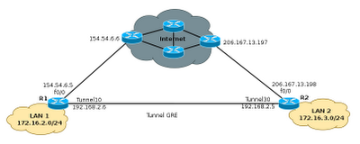
At the end of these configurations, the resulting topology will be as shown in the graph below, with an interface Tunnel10 in router1, connected with a direct cable to Tunnel30 interface on Router 2.

The next step now will allow routing from 172.16.2.0/24 to 172.16.3.0/24. In practice this is simple and does not hit the network performance, thus creating tunneles, can solve many problems of connectivity between remote sites without much complexity. The only thing that should be taken into account when creating the tunneles is no mistakes with the start addresses and destination.
Commands to configure static routing:
Ipip mode is the type of tunnel that allows IP packets encapsulated within another IP packet, very useful to allow communication between IPv6 networks through IPv4 networks. The process for selecting the protocol is simple and need to be configured on both sides of the tunnel, as defined ipip protocol can also select any of the following: AURP, Cayman, dvmrp, eon, gre ip, ip gre multipoint, ipip, iptalk.
It is important to understand the need to make when configuring GRE tunnels, it could be difficult to manage if the number of them grows too. These tunneles turn out to be useful when you need to work with a protocol that is not routable as NetBIOS, or IP routable protocols other than through an IP network. Currently the use of GRE has become a major transition mechanisms for IPv6 network deployment. This means you can connect two IPv6 islands over IPv4 tunnel.

Configuring GRE Tunnels
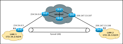
Configure the GRE tunnel is in principle a relatively simple task, just define the start and destination addresses on both devices and create the tunnel interface. To run the example will use Cisco 2800 series routers, although it is possible to make a tunnel with a variety of equipment.Router1#configure terminal Router1(config)#interface Tunnel10 Router1(config-if)#ip address 192.168.2.6 255.255.255.252 Router1(config-if)#tunnel source 154.54.6.5 Router1(config-if)#tunnel destination 206.167.13.198 Router1(config-if)#end Router1#
On Router 2, you must create another tunnel interface, as Router 1, and associate the source and destination addresses.
Router2#configure terminal
Enter configuration commands, one per line.  End with CNTL/Z.
Router2(config)#interface Tunnel30
Router2(config-if)#ip address 192.168.2.5  255.255.255.252
Router2(config-if)#tunnel source 206.167.13.198
Router2(config-if)#tunnel destination 154.54.6.5
Router2(config-if)#end
Router2#
At the end of these configurations, the resulting topology will be as shown in the graph below, with an interface Tunnel10 in router1, connected with a direct cable to Tunnel30 interface on Router 2.

The next step now will allow routing from 172.16.2.0/24 to 172.16.3.0/24. In practice this is simple and does not hit the network performance, thus creating tunneles, can solve many problems of connectivity between remote sites without much complexity. The only thing that should be taken into account when creating the tunneles is no mistakes with the start addresses and destination.
Commands to configure static routing:
Router1(config)#ip route 172.16.3.0 255.255.255.0 tunnel 10 192.168.2.5
Router1(config-if)#end
Router2(config)#ip route 172.16.2.0 255.255.255.0 tunnel 30 192.168.2.6
Router2(config-if)#end
Selecting the type of tunnel to use
When you create a tunnel, usually do not specify the protocol to use, so that devices default, select the GRE protocol. However it is possible to define the protocol, by a single command, as shown below:Router1(config)#interface Tunnel1 Router1(config-if)#tunnel mode ipip
Ipip mode is the type of tunnel that allows IP packets encapsulated within another IP packet, very useful to allow communication between IPv6 networks through IPv4 networks. The process for selecting the protocol is simple and need to be configured on both sides of the tunnel, as defined ipip protocol can also select any of the following: AURP, Cayman, dvmrp, eon, gre ip, ip gre multipoint, ipip, iptalk.
0 Comments:
Post a Comment